Closing the loop: FPGA verification that tunes itself, 24/7
Automating an IC flow isn't about firing steps in sequence — it's about loops that measure a real result and decide whether to go again. I walk through one concrete example: an FPGA-verification loop that programs a real board, reads its LEDs with a camera, and re-runs itself until it converges, with no one sitting in the loop.
Why closed loops are the heart of it
When people picture automating an IC flow, they usually picture a pipeline: fire step one, then step two, then step three, and you're done. That picture is wrong in a way that matters. Automating this flow isn't about firing steps in sequence — it's about loops. A real loop has four moves: transform the design, measure the actual result, decide whether it's good enough, and adjust — then repeat until it converges.
The load-bearing word there is measure. Without a real measurement fed back in, what you have is open-loop: a sequence that runs to the end and looks automatic, but never checks whether the thing it produced is actually right. Closing the loop is the opposite. It means a machine reads the true result — not a predicted one, not an assumed one — and, on the strength of that reading, decides whether to go around again. Everything else in this post is an instance of that one idea.
A concrete loop: FPGA verification
Let me make it physical, because the abstraction only earns trust once you can point at hardware. Here is one loop, end to end.
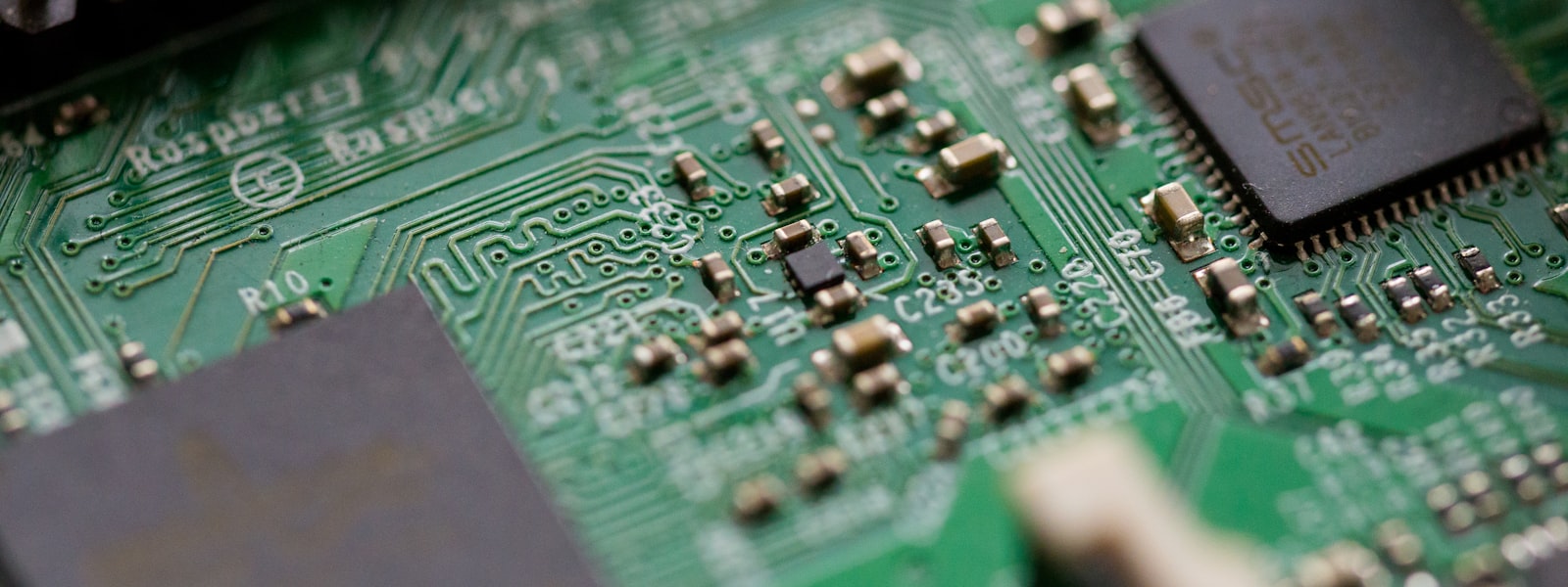
Vibe-IC emits an SOF — the FPGA programming file. That SOF is programmed onto a real FPGA board, an Intel MAX 10 DE10-Lite, over Linux via JTAG. The design now runs on real silicon, not in a simulator. Then a camera reads the board's on-board LEDs and judges whether what the hardware is doing matches what was expected. If it matches, the loop is done. If it doesn't, the loop goes again: adjust, re-program the SOF, re-check the LEDs. That is a full FPGA-verification closed loop, running on physical hardware — the result being measured is the behavior of a real device on a real board, read back by a camera pointed at real light.
What's on the bench, and a nuance about instruments
Three kinds of device are wired into this bench: an FPGA, a scope or logic analyzer, and a camera. There's an important distinction between them that's easy to get wrong.
The scope and the logic analyzer already talk to Linux directly, over their own ports — SCPI over USB and the like. So their waveforms and captured data come back as numbers you can analyze directly. You do not point a camera at an instrument screen and try to read pixels; that would be throwing away the clean digital readout the instrument is already handing you. The camera earns its place for exactly one job: the FPGA's physical LEDs, which have no digital readout at all. There is nothing to query over a port — the only way to know what those LEDs are showing is to look at them. So the rule is simple: instruments are read directly over Linux; the FPGA's LEDs are read by camera.
How the AI actually drives it
The thing that turns this bench into a loop an agent can run is the MCP layer. Every device on the bench sits behind one MCP tool — Vibe-IC's eda-tools MCP. Program an SOF to the FPGA: a tool. Capture the scope: a tool. Diff the camera's LED reading against what was expected: a tool. Every physical action on the bench is a callable function.
Once every device is addressable that way, the AI agent can use each one, pull whatever data it needs, and burn the SOF itself — no human moving cables or clicking through a GUI in between. And that is what closes the loop the whole way. Where an IC-verification engineer used to sit inside that loop — programming the board, watching the LEDs, deciding whether to try again — the agent now runs it, round the clock, unattended. The honest way to describe the gain is not a speed figure; it's that closing the loop takes the human round-trip out of the middle, so the loop can run unattended and keep converging instead of stalling every time it needs a person.
This is only one loop — IC design is loops all the way down
FPGA verification is one loop. It matters because closed-loop convergence is one of the most common and most important processes in the entire flow — the flow is loops all the way down. They come in two kinds.
The first is a single-step loop: local convergence inside one defined step. Each step is one transform plus one checking gate that has to pass, and the step loops on itself until its own gate is green. The second is a cross-step loop: a wider loop that spans several steps and converges the larger result — the outer loop that only closes when a whole span of the flow agrees, not just one gate. Building the entire flow, in the end, means making each of those loops closeable — closeable by a deterministic program first, with an AI backup for the stretches a program can't decide on its own. That's the same program-first, AI-backup, dual-track convergence Vibe-IC runs everywhere else in the flow; the FPGA loop above is just one place you can watch it happen on real hardware.
A close, honestly
These loops are where "AI-native" stops being a slogan and turns into something concrete: a machine that reads a real result and decides, on its own, to go again. That's the whole of it — not a claim about speed, just a claim about closing the gap between doing a thing and checking whether the thing worked. I could be wrong about where the hard parts really are, and there are plenty more loops still to close. But this is the shape I keep coming back to, and I'd rather show you one loop running on a real board than describe ten in the abstract.
That's the loop. In the next post I want to pull back from the hardware and talk about a more personal choice: within this whole flow, which large language model should sit in the driver's seat — and why I ended up betting on Claude.
Further reading: the whole pipeline these loops live inside is on the Flow page, and the hands-on details are in the Manual.